 |
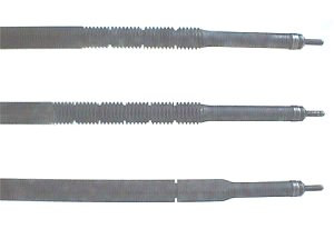
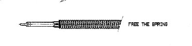
| Top to bottom: original 3-position, current 5-position, and "high energy." (The apparent curvature is due to optical distortion in the photograph.) The new non-adjustable firing pin is round rather than square in cross section. |
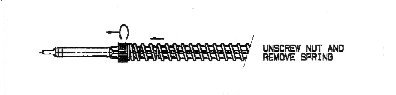
However, if you encounter light hits, before doing anything else you should first perform the following check out or have it performed by a reliable gunsmith familiar with the Steyr Scout.
These instructions assume you are familiar with the disassemble of the bolt. Refer to your owner's manual for parts identification. If you want I can do the bolt tuning for you. See the "Parts" page for details.
There are three variations of the firing pin used in the Steyr Scout. These directions apply to all variations. The original firing pin had 3 adjustment positions. This was modified to 5 positions around October 1998 to provide two additional heavier settings. The factory position on both variations is the second position from the front. There is no reason for owners of the 3-position firing pin to upgrade to the 5-position model especially if the steps outlined below are taken.
The other variation is the firing pin used in the so-called high energy kit which has only one position and is used with a much heavier spring.
|
| Top to bottom: original 3-position, current 5-position, and "high energy." (The apparent curvature is due to optical distortion in the photograph.) The new non-adjustable firing pin is round rather than square in cross section. |
Bolt/Firing Pin Check
 |
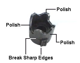
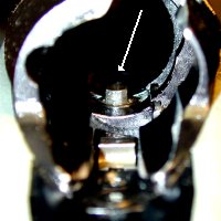
| Firing Pin Stop Area |
Of the 44+ bolts that I know that have been worked on the light hit problem was eliminated in all but 2 bolts, and I suspect headspace issues were the culprit. Follow the directions and proceed carefully. Remember, you are not changing any contours or removing metal. You are just deburring and polishing.
If you are not sure of your abilities to do this you can contact me about having it done by clicking here.
Parts needed: Very fine stone, 220, 400, 600, and
1500 grit
carbide paper. (Emery, crocus cloth, or a Dremel tool with hard felt
wheels and rouge, optional.) Cleaning solvent, lubricant.
(I recommend the aerosol TW25B aerosol as being particularly good with the Scout.)
If you continue to get light hits after this procedure or plan on using the rifle under
extremely cold conditions try a higher spring setting or consider installing either the
"high energy" firing pin kit, officially described as
"Firing pin and spring for MilSpec primers" which is simply a complete
non-adjustable firing pin assembly from the standard SBS rifle. (The high energy
firing pin should also be "deburred" as described above.) The HE firing
pin kit can also be duplicated by installing a heavier spring on the Steyr Scout’s
firing pin and using the first position on the adjustable firing pins without the
nut. There had been a lot of confusion as to what replacement spring
was correct for use with the existing "adjustable" firing pin in the Scouts,
related primarily to the fact that Steyr and GSI used different part numbers. Here is the
official word on the subject. The factory issued "high energy" firing pin kit can be effectively duplicated
by replacing the standard Steyr Scout spring (37 coils) with an 54 coil SSG spring (GSI part
MAN0403B/Steyr part 2900040005). The standard 61 coil SBS spring (GSI part SBS4.3A/Steyr part
24-04009) spring may also be used, but because of its longer length (61 coils vs. 54 for
the SSG spring) difficulties may be encountered if used on the "adjustable"
firing pin assembly of the Scout. Either heavy spring MUST be installed using the lowest compression setting of the
adjustment on the firing pin (first notch) and the factory recommends that the adjusting
nut be omitted, (just use the clip) especially with the SBS spring or blocking may occur.
Bolt lift WILL be increased. Note that the new long springs are quite stiff and if you are not
sure of your abilities you may want to have a gunsmith install the spring for
you as there is a "flying spring" injury potential. Step 1
Firing Pin
Cam Sleeve Area
of Bolt
Firing Pin Lug
Cam Sleeve
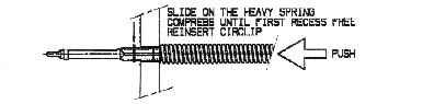
Step 3
The following tool can assist in the installation of the firing pin. Simply compress the spring with the tool, install the thrust washer/clip, and slide the tool off.
| Related Part Number Reference | ||
| Item | GSI Part # | Steyr Part # |
| Steyr Scout Spring (Light-37 coils) | SC 04.22 | |
| High Energy Firing Pin Kit | SC 04.09AH | |
| SSG Spring (Heavy-54 coils) | MAN 0403B | 2900040005 |
| SBS Spring (Very Heavy-61 coils) | SBS4.3A | 24-040009 |
| Trust Washer/Clip (Spare) | SC 04.25 | 190003936613 |
Tip: Should you lose your thrust washer it can be replaced by a generic 4.8 mm (3/16") "EC-18" clip available at many well stocked hardware stores like ACE.
If you are not sure of your ability to do the bolt tune up procedure and would like to have the work done for you please contact me by clicking here for further information.
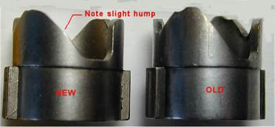
The factory is aware of the bolt lift effort issue raised by some people. Due to the physical design of the bolt with its 60 degree rotation and short firing pin travel distance (for quick lock time) there is not much that can be done to eliminate this problem at the current time. Steyr has recently come up with an improved design cam sleeve that incorporates a double angle primary cam that improves the bolt lift. It seems to be coming through on new (late 2004 and later) guns and coupled with the polishing process makes bolt lift a lot easier. As far as I know the new cam is NOT available for after market purchase. If you lay a straight edge along the long slope of the cam and it fits flush you have the old cam.
 |
However, I occasionally (thanks to the "parts fairy") have a limited number of these improved cams available for retrofitting to older rifles. For a list of parts I have in stock and cost click here. For further information contact me by clicking here.
In addition, check the face of the ejector button for burrs or any roughness and for a full range of smooth movement in and out. If there are any rough spots carefully remove the ejector and polish it.. Early ejectors were flat across the face and can have sharp edges both of which can contribute to heavy bolt lift. If you have the early flat ejector, remove the ejector and carefully round the tip and polish. |
| Ejector shapes |
Also, insert the bolt shroud (minus the firing pin assembly) into the bolt and check for smooth rotation. Carefully deburr the lugs if any interference is noted.
LIGHTLY apply a quality lubricant to all bearing surfaces. Reassemble the bolt and apply a light coating of lubricant to the bolt body, bolt raceway in the receiver, and a little on the cylindrical portion on the locking lug area of the bolt.
I'd like to acknowledge the contributions made by Rich Lucibella and Elmar Bilgeri whose help made these procedures possible.
Smoothing Up Bolt Travel
Bolt travel can be significantly smoothed up and binding eliminated on Steyr Scouts by slightly beveling the two opposite edges of the guiding pin protruding into the guide rail of the bolt. About 1/32" (1 mm) downwards, at about a 10° slope (basically just break and smooth the edges). You can also check the pin guide slot in the bolt body for any roughness too. Just smooth up any noticeable burrs or rough edges. Add some proper lubrication and you have a much smoother bolt without any binding. Steyr is reportedly implementing this tip on future production.
 |
![Pin location in trigger group [3k gif]](pinloc.gif) |
![guide pin detail [2k gif]](pin.gif) |
| Bolt guide pin | Location of guide pin in trigger group | Modification |
The pin is part of the trigger group. To access the guide pin remove the bolt and put the safety in the "fire" position. The pin will stick up and can be seen just forward of the sear head. The edges can be beveled with a very fine long stone or diamond file. Steyr specifically warns against removing the trigger assembly to do this as you will void your warranty but if you know what you are doing it is not a major task..
Some Background On The Causes Of These Problems
After some investigation and cajoling of factory sources it appears that the above issues are caused by several things in the rifle's design.
Light hits are caused by several factors. First, because of the mechanical requirements of the "Double Lock/Safe" position of the bolt the rifles are chambered with a maximum headspaced chamber (under European CIP specification) to ensure free bolt movement with maximum specification ammunition. Most of the Scouts I have tested will close on a SAAMI "NOGO" (1.634") gauge but not on a "FIELD" (1.638") gauge. However, with average or minimum specification cases ( the norm) this allows a little slop in chambering which dampens the firing pin hit. If the ammunition also has harder than normal primers light hits can result. If your Steyr will close easily on a SAAMI field gauge you should probably contact Steyr US about having the headspace tightened up a bit. If you are handloading for your Steyr Scout you should adjust your sizing die to ensure that the shoulder of the case is not pushed back too far and that the shoulder distance stays as close to the fired case dimension as possible.
Second, the Steyr Scout uses a bolt with only a 60 degree lift and a short stroke firing pin (for fast lock time). The short firing pin travel and the need to impart enough kinetic energy to the pin requires a fairly stiff spring. While one can use a even stiffer spring (or adjust the factory spring to the maximum tension setting) to get enough firing pin energy to overcome the chamber slop and to fire just about anything this adversely affects bolt lift.
The 60 degree bolt lift requires a fairly steep slope on the cocking cam which is what causes the heavy bolt lift. Without going to a minimum or average specification chamber or redesigning the action to give a longer firing pin travel there is nothing that can be done other than what is described above to improve the Scouts performance. [2004 - Steyr is slipstreaming an improved bolt cam that changes the force needed to lift the bolt and improves the feel. These cams are not currently offered as an after market accessory but contact me by clicking here if you are interested in more information.]
Also, the ammunition reported as giving light hits is almost exclusively military surplus and checking these cartridges in a case gauge indicates that in every case these rounds are at or below minimum base to shoulder measurement. I have measured many rounds of surplused ammo that have been .002 under minimum. In addition I have observed many rounds with very deeply seated primers which causes its own set of problems. Several source have indicated that military ammunition tends to be made on the small size of tolerances to allow for functioning under adverse conditions and military firearms are designed to handle this. In addition, surplus ammunition was surplused for a reason and some of it may in fact be out of spec.
The polishing steps outlined above help to ensure that there will be no internal drag and that the firing pin will generate maximum kinetic energy.
Email me by clicking here.
| Return to the Tips & Tricks Page |
Disclaimer
Neither Fr. Frog, the hosting service for these pages, nor this page is officially associated with Steyr Mannlicher, AG, nor Steyr Mannlicher USA. These tips provided by Fr. Frog as a service to the friends of Jeff Cooper, the folks Steyr, and the shooting community. Fr. Frog is not responsible for any errors, omissions, nor your inability to hit what you aim at when using this rifle. As far as I know all the information presented is correct and I have attempted to ensure that it is. However, I am not responsible for any errors, omissions, or damages resulting from the use or misuse of this information, nor for you doing something stupid with it. (Don't you hate these disclaimers? So do I, but there are people out there who refuse to be responsible for their own actions and who will sue anybody to make a buck.)
![]()
Updated 2012-08-11